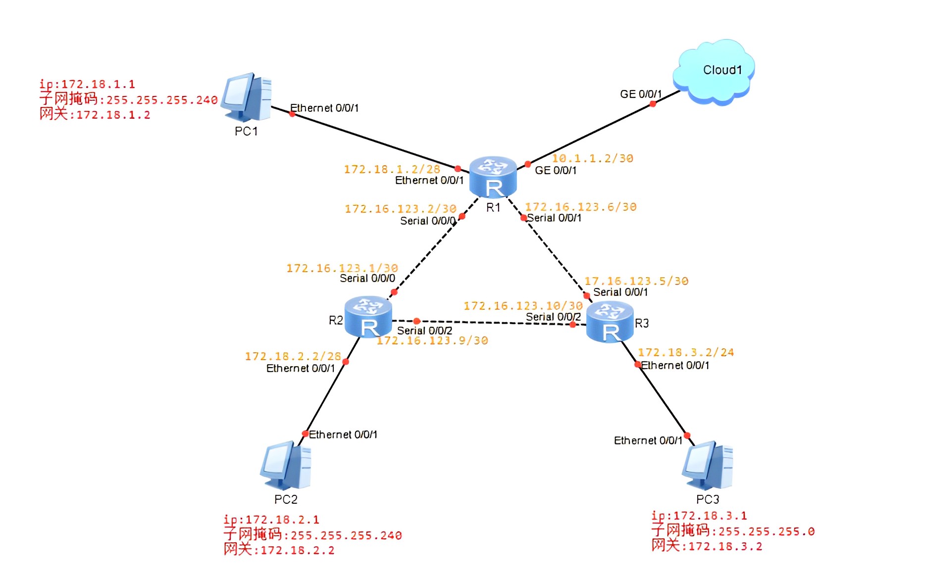
设备网络参数和连接
| 设备名 | 地址 | 网关 | 子网掩码 |
|---|---|---|---|
| PC1 | 172.18.1.1 | 172.18.1.2 | 255.255.255.240 |
| PC2 | 172.18.2.1 | 172.18.2.2 | 255.255.255.240 |
| PC3 | 172.18.3.1 | 172.18.3.2 | 255.255.255.0 |
| R1|e0/0/1 | 172.18.1.2/28 | 无 | 无 |
| R1|s0/0/0 | 172.16.123.2/30 | 无 | 无 |
| R1|s0/0/1 | 172.16.123.6/30 | 无 | 无 |
| R1|g0/0/1 | 10.1.1.2/30 | 无 | 无 |
| R2|s0/0/0 | 172.16.123.1/30 | 无 | 无 |
| R2|s0/0/2 | 172.16.123.9/30 | 无 | 无 |
| R2|e0/0/1 | 172.18.2.2/28 | 无 | 无 |
| R3|s0/0/1 | 17.16.123.5/30 | 无 | 无 |
| R3|s0/0/2 | 172.16.123.10/30 | 无 | 无 |
| R3|e0/0/1 | 172.18.3.2/24 | 无 | 无 |
注意255.255.255.240的掩码位数是28 注意255.255.255.0的掩码位数是24。28-24=4,即掩码是11110000,转换成十进制也就是我们写的240
注意Cloud1不需要配置ip,这里没什么作用
| 源设备名称 | 设备端口 | 端口描述 | 目标设备名称 |
|---|---|---|---|
| PC1 | e0/0/1 | 无 | R1 |
| R1 | e0/0/1 | 无 | PC1 |
| R1 | s0/0/0 | 无 | R2 |
| R1 | s0/0/1 | 无 | R3 |
| R1 | g0/0/1 | 无 | Cloud1 |
| Cloud1 | g0/0/1 | 无 | R1 |
| R2 | s0/0/0 | 无 | R1 |
| R2 | s0/0/2 | 无 | R3 |
| R2 | e0/0/1 | 无 | PC2 |
| R3 | s0/0/1 | 无 | R1 |
| R3 | s0/0/2 | 无 | R2 |
| R3 | e0/0/1 | 无 | PC3 |
| PC2 | e0/0/1 | 无 | R2 |
| PC3 | e0/0/1 | 无 | R3 |
注意:Clound1这个云默认是没有端口的,解决如下 双击Cloud1,在端口类型右侧选择GE,点击右侧的添加按钮
实验过程
1、配置PC1、PC2、PC3、PC4的ip
2、配置R1的各个端口的ip。双击R1
xxxxxxxxxxsysun in ensys R1int e0/0/1ip add 172.18.1.2 28int g0/0/1ip add 10.1.1.2 30int s0/0/0ip add 172.16.123.2 30int s0/0/1ip add 172.16.123.6 30
2、配置R2的各个端口的ip。双击R2
xxxxxxxxxxsysun in ensys R2int e0/0/1ip add 172.18.2.2 28int s0/0/0ip add 172.16.123.1 30int s0/0/2ip add 172.16.123.9 30
3、配置R3的各个端口的ip。双击R3
xxxxxxxxxxsysun in ensys R3int e0/0/1ip add 172.18.3.2 24int s0/0/1ip add 17.16.123.5 30int s0/0/2ip add 172.16.123.10 30
4、配置R1的rip协议。双击R1 注意:配置rip协议只看最前面那位的数字,比如192,就配置为192.?.?.0 比如172,就配置为172.?.0.0,比如10,就配置为10.0.0.0 分析:R1的e0/0/1端口的网络地址是172.18.1.0 R1的s0/0/0端口的网络地址是172.16.123.0 R1的s0/0/1端口的网络地址是172.16.123.0 R1的g0/0/1端口的网络地址是10.0.0.0
xxxxxxxxxxripnetwork 10.0.0.0network 172.18.0.0network 172.16.0.0
5、同理配置R2的rip协议。双击R2 分析:R2的e0/0/1端口的网络地址是172.18.0.0 R2的s0/0/0端口的网络地址是172.16.0.0 R2的s0/0/2端口的网络地址是172.16.0.0
xxxxxxxxxxripnetwork 172.18.0.0network 172.16.0.0
6、同理配置R3的rip协议。双击R3 分析:R3的e0/0/1端口的网络地址是172.18.0.0 R3的s0/0/1端口的网络地址是172.16.0.0 R3的s0/0/2端口的网络地址是172.16.0.0
xxxxxxxxxxripnetwork 172.18.0.0network 172.16.0.0
7、查询路由表信息
xxxxxxxxxxdis ip routing
8、拓展:把每个路由的rip协议的版本修改为2 双击R1
xxxxxxxxxxversion 2
双击R2
xxxxxxxxxxversion 2
双击R3
xxxxxxxxxxversion 2
9、查询路由表信息。注意这次查询的路由表信息跟第7步骤查询的信息不同,这次的信息更详细
xxxxxxxxxxdis ip routing
实验验证
第7个步骤完整之后,双击PC2,就可以完成如下验证了
xxxxxxxxxxping 172.18.3.1ping 172.18.1.1
可以发现我们ping不通172.18.1.1,但是输入tracert 172.18.1.1是可以正常通过数据的 原因:PC2到PC1之间的跳数超过了8,因此无法ping通,这不是由于命令出现错误,而是一个规则 解决:把R2的s0/0/0端口的优先级改小一些 新问题:改了优先级之后,就会导致PC3和PC1之间的跳数超过8,所以上一个问题是没必要解决的问题 再次强调命令是没问题的哦
第7步骤的后续的步骤只是演示不同的rip协议版本查询到的路由表信息的差别有那些