MSTP新知识点
回顾之前学过的生成树协议
- STP生成树协议:消除环路
- RSTP快速生成树协议:在STP基础上进行了改进,实现了网络拓扑快速收敛
STP/RSTP的局限
- 所有VLAN共享一颗生成树
- 无法实现不同VLAN在多条Trunk链路上的负载分担
MSTP(多生成树协议)
- 基于实例计算出多颗生成树,实例间实现负载分担
- 具有RSTP的快速收敛,同时又具有负载分担的机制
- 兼容STP和RSTP
MSTP基本思想
- 为每个实例算出一颗生成树,交换机上可以配置多个实例,算出多颗生成树
- 为每个实例包含一个或者多个VLAN
- VLAN会按照所在实例的生成树结构转发数据
- 从而实现不同VLAN之间的负载分担
MSTP域
- 不同域之间相互独立
- 交换机只有处于同一MSTP域中,才能体现MSTP负载分担的优势
- 如果出现不同的域,会出现一个新的端口角色--master端口 简单理解就是用来存放mstp的相关配置
判断处于同一MSTP域的条件,需要都满足
- 域名
- 修订级别:目前保留,默认为0
- vlan映射:指vlan与实例的映射关系
注意下面的拓扑演示是包含一点点上节课的VRRP协议的知识,就当复习啦
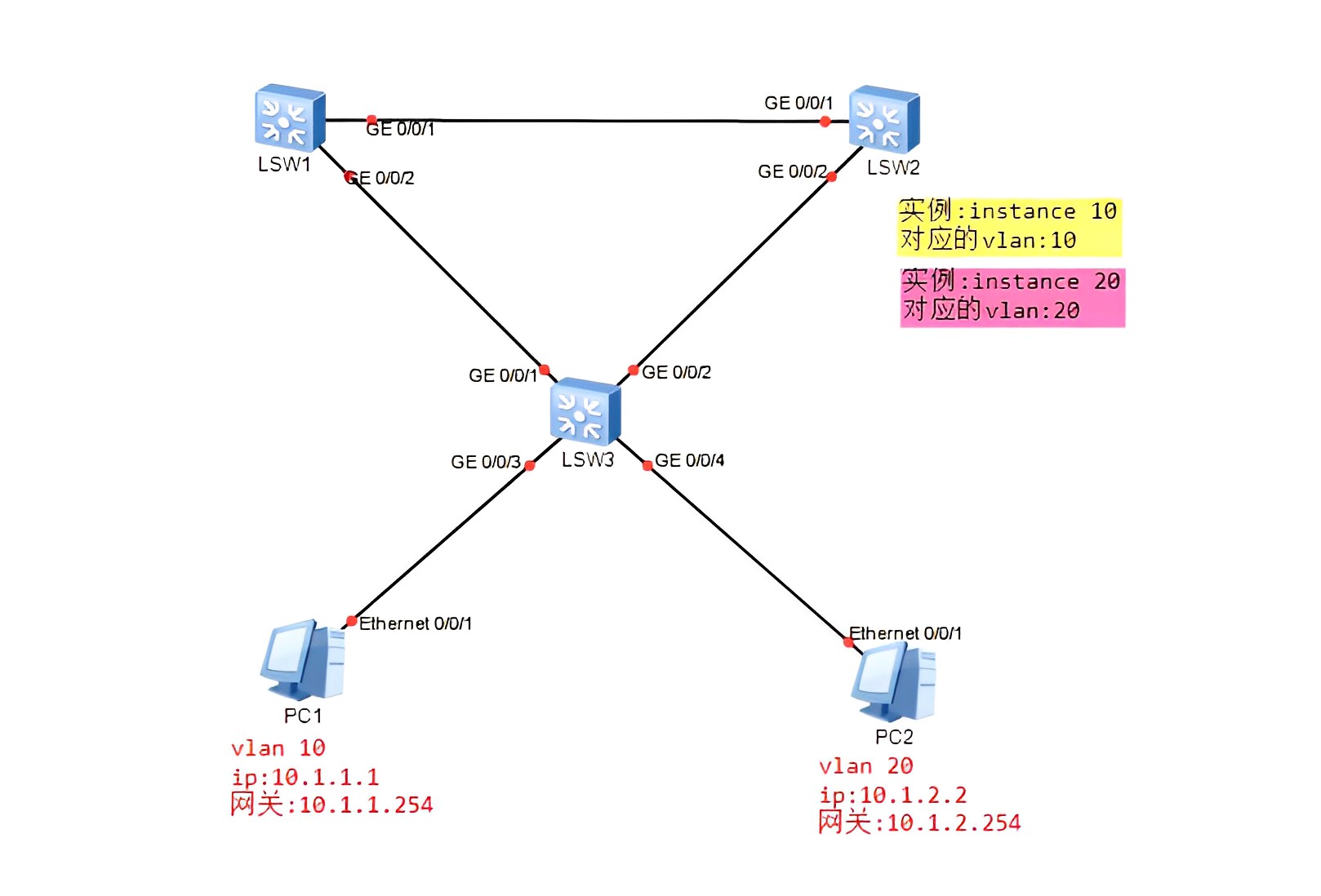
设备网络参数和连接
| 设备名 | 地址 | 网关 | 子网掩码 |
|---|---|---|---|
| PC1 | 10.1.1.1 | 10.1.1.254 | 255.255.255.0 |
| PC2 | 10.1.2.2 | 10.1.2.254 | 255.255.255.0 |
| 源设备名称 | 设备端口 | 端口描述 | 目标设备名称 |
|---|---|---|---|
| LSW1 | g0/0/1 | 无 | LSW2 |
| LSW1 | g0/0/2 | 无 | LSW3 |
| LSW2 | g0/0/1 | 无 | LSW1 |
| LSW2 | g0/0/2 | 无 | LSW3 |
| LSW3 | g0/0/1 | 无 | LSW1 |
| LSW3 | g0/0/2 | 无 | LSW2 |
| LSW3 | g0/0/3 | 无 | PC1 |
| LSW3 | g0/0/4 | 无 | PC2 |
| PC1 | e0/0/1 | 无 | LSW3 |
| PC2 | e0/0/1 | 无 | LSW3 |
注意要保证生成树的根桥vrrp的master在同一台设备上面,就是最优方式
实验要求
- 使用MSTP协议,模拟故障,使得PC1和PC2的正常通信
实验过程
1、配置PC的ip
2、创建两个vlan,把各个端口添加到对应的vlan。双击LSW3
xxxxxxxxxxsysun in ensys SW3vlan batch 10 20int g0/0/1port link-type trunkport trunk allow-pass vlan 10 20int g0/0/2port link-type trunkport trunk allow-pass vlan 10 20int g0/0/3port link-type accessport default vlan 10int g0/0/4port link-type accessport default vlan 20
3、创建两个vlan,把各个端口添加到对应的vlan。双击LSW1
xxxxxxxxxxsysun in ensys SW1vlan batch 10 20int g0/0/1port link-type trunkport trunk allow-pass vlan 10 20int g0/0/2port link-type trunkport trunk allow-pass vlan 10 20
4、创建两个vlan,把各个端口添加到对应的vlan。双击LSW2
xxxxxxxxxxsysun in ensys SW1vlan batch 10 20int g0/0/1port link-type trunkport trunk allow-pass vlan 10 20int g0/0/2port link-type trunkport trunk allow-pass vlan 10 20
5、分别查看3个路由器的vlan配置。分别双击LSW1、LSW2、LSW3,输入如下
xxxxxxxxxxdis port vlan
6、修改生成树的模式为mstp,配置mstpd域即把vlan10绑定到实例10里面、把vlan20绑定到实例20里面, 使用active来激活域,双击LSW3
xxxxxxxxxxsysun in enstp mode mstpstp region-configurationinstance 10 vlan 10instance 20 vlan 20active region-configuration
查看当前配置
xxxxxxxxxxdis this
7、同理,配置LSW1的mstp。双击LSW1
xxxxxxxxxxsysun in enstp mode mstpstp region-configurationinstance 10 vlan 10instance 20 vlan 20active region-configuration
8、同理,配置LSW2的mstp。双击LSW2
xxxxxxxxxxsysun in enstp mode mstpstp region-configurationinstance 10 vlan 10instance 20 vlan 20active region-configuration
9、此时我们已经在LSW1 -> LSW2 -> LSW3 的二层网络上创建了两个实例,或理解为我们给这个二层 网络运行了两个生成树,一个是instance10的生成树、另一个是instance20的生成树。后续vlan10的 数据就会按照instance10计算出来的数据走,vlan20数据就会按照instance20计算出来的数据走。 查看stp的配置
xxxxxxxxxxdis stp brief
10、双击LSW3
xxxxxxxxxxdis stp brief
会发现LSW3的所有的端口都是DEST(指定端口),所以LSW3就是根桥。会造成LSW1-LSW3 和 LSW2-LSW3 这两条链路是通的,而LSW1-LSW2这条链路是堵的,会导致LSW1到LSW2的vrrp数据绕行,即LSW1到LSW2 的数据是走LSW1->LSW3->LSW2这条路,就造成了LSW1到LSW2的vrrp数据流向是次优的。 解决:不能让根桥是LSW3,也就是不能让根桥在接入层的位置 做法:把实例10,即把instance10的根桥设在LSW1。把实例20,即把instance20的根桥设在LSW2。
下面是指定根桥的具体输入:
双击LSW1
xxxxxxxxxxsysstp instance 10 root primary
完成上面那行的输入后,此时LSW1设备就是实例10的根桥啦 查看LSW1是不是根桥
xxxxxxxxxxdis stp brief
发现g0/0/2端口的ROLE列就变成了Root,也就是LSW1的g0/0/2是实例10的根桥
同理双击LSW2
xxxxxxxxxxsysstp instance 20 root primary
完成上面那行的输入后,此时LSW1设备就是实例20的根桥啦 查看LSW2是不是根桥
xxxxxxxxxxdis stp brief
发现g0/0/2端口的ROLE列就变成了Root,也就是LSW2的g0/0/2是实例20的根桥
此时,例如对于实例10来说 实例10的根桥在LSW1,那么阻塞的链路就是LSW2-LSW3这条链路,我们的LSW2-LSW1 和 LSW1-LSW3这 两条链路都是连接根桥的(根桥是LSW1,对于实例10来说),所以这两条链路不可能阻塞,那么PC1的数据
流向就是PC1->LSW3->LSW1,并且vrrp的数据流向是LSW1->LSW2,也就是此时vrrp的数据流向也是最优路径
此时,例如对于实例20来说 实例20的根桥在LSW2,那么阻塞的链路就是LSW1-LSW3这条链路,我们的LSW1-LSW2 和 LSW2-LSW3这 两条链路都是连接根桥的(根桥是LSW2,对于实例20来说),所以这两条链路不可能阻塞,那么PC2的数据 流向就是PC2->LSW3->LSW2,并且vrrp的数据流向是LSW1->LSW2,也就是此时vrrp的数据流向也是最优路径
11、配置vrrp。双击LSW1
xxxxxxxxxxsysint vlanif 10ip address 10.1.1.251 24vrrp vrid 1 virtual-ip 10.1.1.254vrrp vrid 1 priority 200int vlanif 20ip address 10.1.2.251 24vrrp vrid 2 virtual-ip 10.1.2.254
11、配置vrrp。双击LSW2
xxxxxxxxxxsysint vlanif 10ip address 10.1.1.252 24vrrp vrid 1 virtual-ip 10.1.1.254int vlanif 20ip address 10.1.2.252 24vrrp vrid 2 virtual-ip 10.1.2.254vrrp vrid 2 priority 200
12、查看vrrp配置。分别双击LSW1、LSW2、LSW3,输入如下
xxxxxxxxxxdis vrrp brief
实验验证
双击PC1,输入如下
xxxxxxxxxxipconfigping 10.1.1.254
双击PC2,输入如下
xxxxxxxxxxipconfigping 10.1.2.254ping 10.1.1.1
模拟LSW1-LSW3这条链路发生故障,双击LSW3
xxxxxxxxxxint g0/0/1shutdown
然后双击PC2,输入如下
xxxxxxxxxxping 10.1.1.1